Pasta Maker Press
A PDF version can be downloaded here: How To Make A Pasta Maker Printing Press
I have always heard that small etchings can be made using a pasta maker, but never tried it myself.
Most of the videos I’ve seen using the pasta machine use it in the vertical position, which looks cumbersome. Since you have to vertically feed the work and bend it on the way out. So decided to try it myself, only using it horizontally, and not knowing anything pasta makers, meaning what are good one and bad ones. I purchased an inexpensive one on Amazon:
Nuvantee Pasta Maker - Highest Quality Pasta Machine - 150 Roller with Pasta Cutter - 7 Adjustable Thickness Settings
The second reason I chose this particular pasta maker was its thinkness range was 2mm to 6mm. The more expensive pasta makers focused on thinner pasta. I wanted greatest separation between the rollers as possisble.
Materials
Materials Purchased:
Nuvantee Pasta Maker on Amazon - For $35.95, it also came with one attachment and a clamp, which I didn't need.
Additional materials purchased at Lowes ($32.87):
- 1 - 1"x8"x48" pine board (actual dimensions 3/4"x7-1/4"x48") - $6.99
- 1 - 1"x6"x48" pine board (actual dimensions 3/4"x5-1/2"x48") - $4.45
- 1 - 1"x2"x48" pine board (actual dimensions 3/4"x1=1/2"x48") - $1.85
- 1 - 1/2"x2"x48" poplar board (actual dimension 1/2"x1-1/2"x48") - $3.99
- 1 - 1/4"x6"x24" poplar board (actual dimension 1/4"x5-1/2"x24") - $3.40
- 1 - 6"x18" Very thin aluminum sheet (0.025in) - $9.49
- 1 - 1/8"x36" wooden dowel - $0.63
- 1 - Elmer's Wood Glue - $2.07
Additional Materials Used:
- 24 - 1" phillips head wood screws
Minimum Tools needed:
- Phillips Screwdriver
- Flat Screwdriver
- Hand or Electric drill with 1/8", 3/16" and 3/8" drill bits
- Hand or Electric Saw
I used an electric mitre saw to cut the wood, a drill press for most of the holes, a large vice for glueing the side rails and electric drill with a phillips screw driver bit to put it together.
Unboxing Pasta Maker
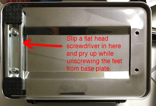
By far the most frustrating part of this projects was removing the base from the pasta maker, it looked easy, there were just 4 phillips head screws that had to be removed, however the "nut" that's inaccessible on the inside of the pasta maker just spins with the screw when it was turned. I needed to slip a flat headed screw driver under the foot bar, which put pressure on the nut, and I was able to slowly get the base off. It took about a 30 minutes to remove all 4. If you have a small hacksaw, once they are loosened a little, it might be easier to cut them off, just a warning on this pasta maker brand.
Building the Pasta Press
After removing the base, I took some measurements:
- The pasta maker “legs” were 5-5/8 inches apart
- The “legs” were 1/2 inch by 2-7/8 inches
- The bottom pasta roller was 2-3/4 inches
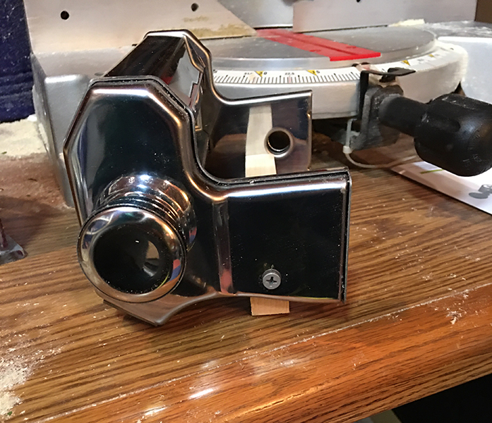
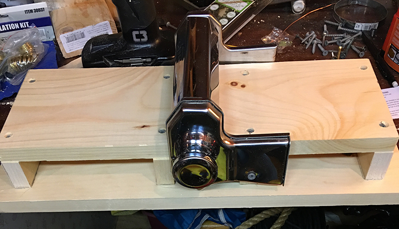
I decided the best way to attach the pasta maker to a base board was to by using a cross support between the legs (3/4 x 1-1/2 x 5-5/8 inches), using a right angle to level the maker and marked the locations to drill a 3/16 hole.
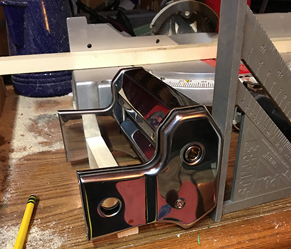
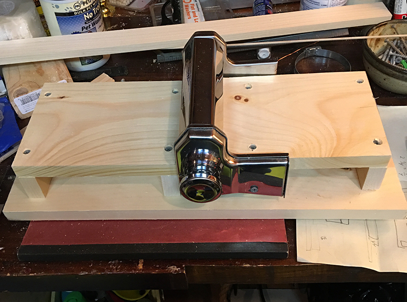
In the following picture you can see the attached cross support
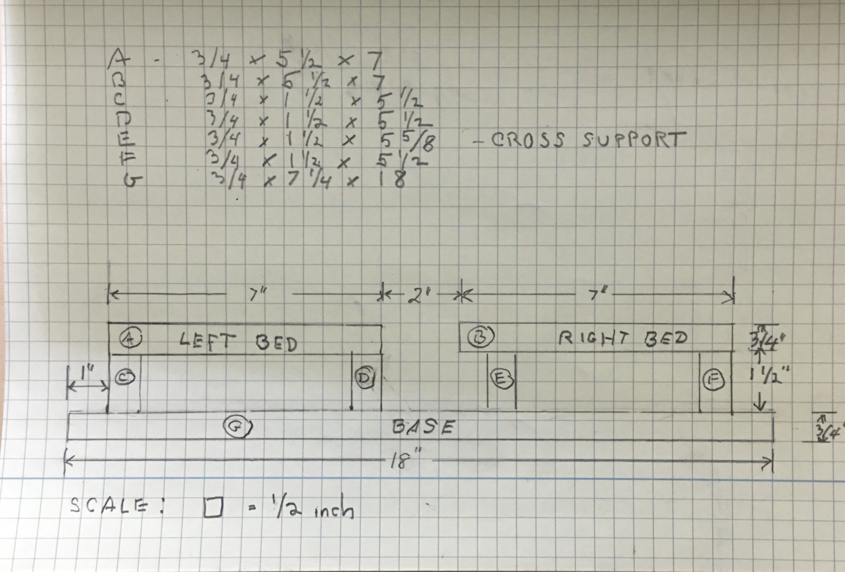
The next step, cut the remaining pieces for the pasta maker press:
- Base: 3/4 x 7-1/4 x 18 inches
- Left Bed: 3/4 x 5-1/2 x 7 inches
- Right Bed: 3/4 x 5-1/2 x 7 inches
- Left Bed Support:
2 pieces - 3/4 x 1-1/2 x 5-1/2 inches - Right Bed support:
1 piece - 3/4 x 1-1/2 x 5-1/2 inches
1 piece - 3/4 x 1-1/2 x 5-5/8 inches (Cross Support)
The position of the Cross Support is really depended on where it is attached between the pasta maker legs.
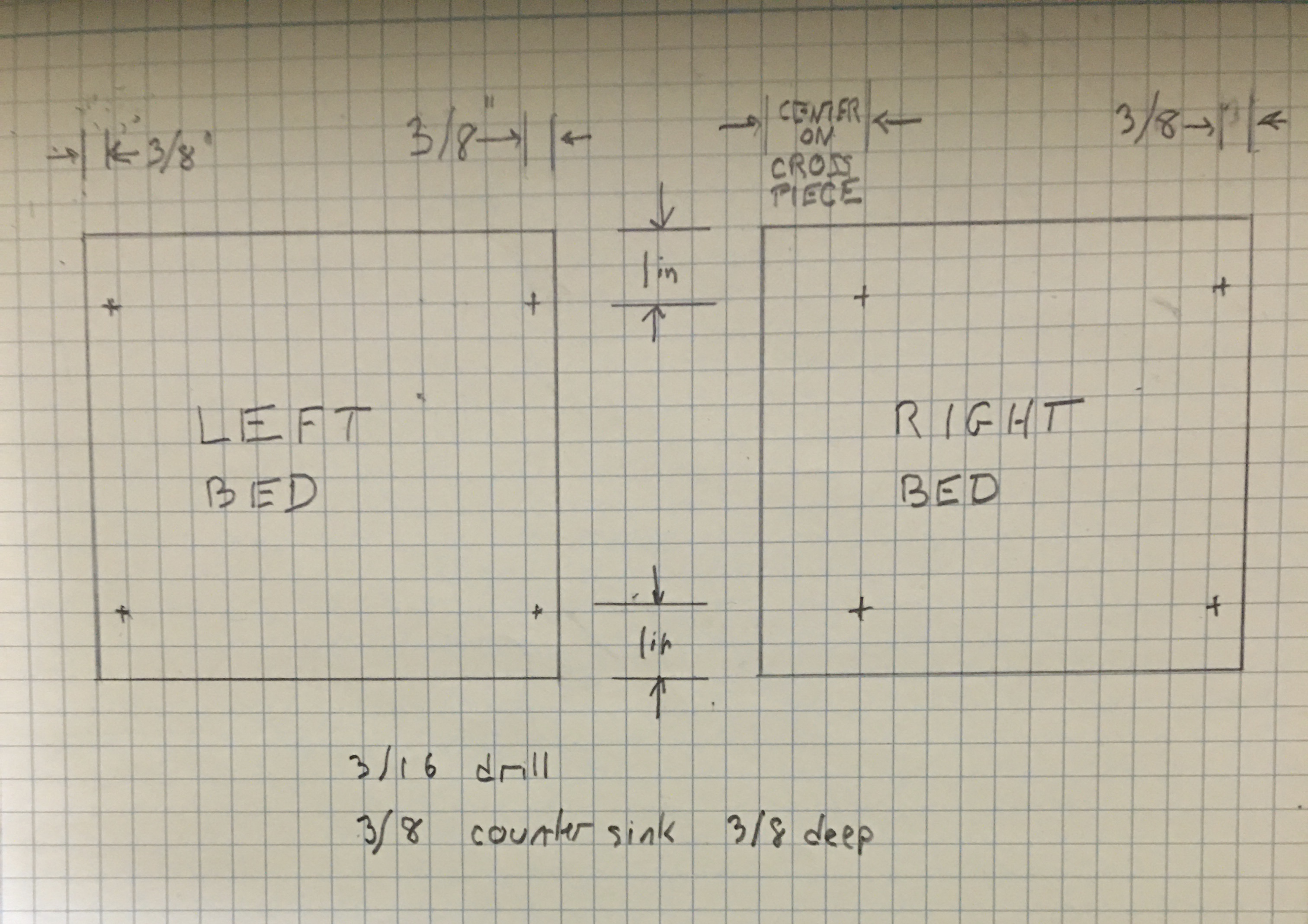
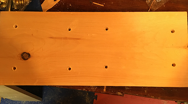
Drill four 3/16 inch holes in each bed to line up with the bed support pieces:
Each hole should be counter sunk 3/8” using a 3/8” drill bit, so that the screws are below the bed surface when the support pieces are attached.
Apply glue to the support pieces on the left bed and screw on the bed with the 1” wood screws, repeat on the right side. Glue the cross support and last support piece and attach the right bed.
The center the two pieces on the base board.
Next, draw a line around the edges of the support pieces. So you end up with something that looks like:
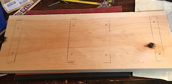
The drill two 3/16 in holes for each sport piece, again counter sinking 3/8” deep with a 3/8” drill bit.
Attach the two pieces to the base board with eight 1in wood screws.
You can stop here, or attach the side rails.
- Cut four pieces of the poplar board: 1/2 x 1-1/2 x 7”
- Cut four pieces of the poplar board: 1/2 x 1-1/2 x 4-1/4”
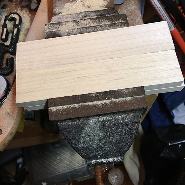
Drill 1/8” holes 1/2” deep for the 1/8” dowel. Take care here to make sure the holes line up correctly, and glue the pieces together:

Once they are glue together, clamp them for a tight fit.
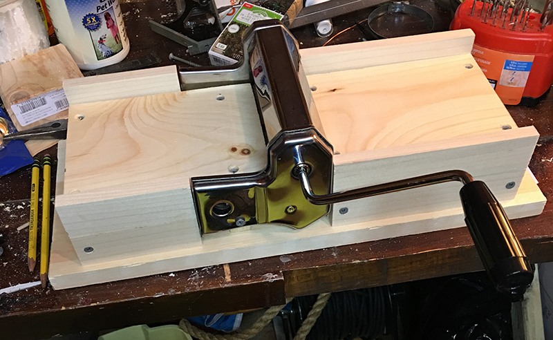
Once you have finished creating the rails for each bed, drill 3/16” holes in each piece to line up with the support piece ends, (counter sink if desired) glue and screw together with the 1in wood screws. The final press should look like:
I also cut two pieces of the 1/4" poplar board: 5-1/5" x 7", this raises the bed to be just above level with the bottom roller, in actual use I found I like having the bed level on the side that feeds into the press, and missing on the out side.
You can paint or stain it as desired. That’s it, you are ready to try making a print. The extra 1" on the ends is to allow space for drilling holes to attach to another surface or for clamps.